
The function test of the RF Power Amplifier
2022-10-31
Shenzhen Texin Electronics Co., Ltd is the leading RF power amplifier manufacturer in China. For improving the function and performance of the RF power amplifier, we made a series of test process recently. The RF power amplifier is the core component of signal jammers, function test is very important part before signal jammer assembly, let us show you as below:
Instruments:
|
NO. |
Name |
Model |
QTY |
Mark |
|
1 |
Spectrum Analyzer |
N9000A |
1 |
BW set as 8Mhz |
|
2 |
DC power supply |
SS-3020KDS |
1 |
Voltage28V Current 20A |
|
3 |
Attenuator |
ND638 |
1 |
Frequency support 0- 6Ghz Power support 250W |
|
4 |
RF coaxial cable |
|
Some |
Frequency support 0- 6Ghz Power support 250W |
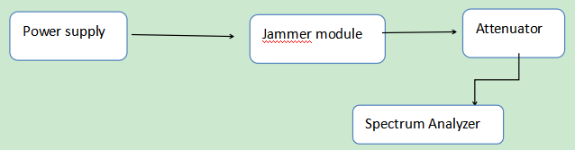
Connection diagram
![]()
![]()
Test instruction
l Confirm whether the equipment used is within the product testing range,
Ø the frequency of the spectrum analyzer is greater than 6Ghz and
Ø the BW can be set to 8Mhz;
Ø the DC power supply has a voltage greater than 28V and has a load capacity of more than 15A;
Ø the frequency of the attenuator is greater than 6Ghz and can withstand 250W power; RF cable Completely intact, etc.
l Sets and calculate Compensate for attenuation
Ø Set the center frequency of the spectrum analyzer to the center frequency of the product under test,
Ø set the bandwidth to 500Mhz,
Ø set the BW to 8Mhz,
Ø compensate the insertion loss of the attenuator and the RF cable into the Spectrum Analyzer
Ø set the appropriate attenuation level according to the power of the product.
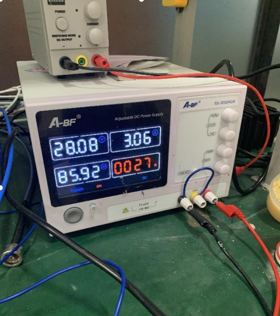
l Adjust the power supply voltage to 28V and the power supply current to the maximum.
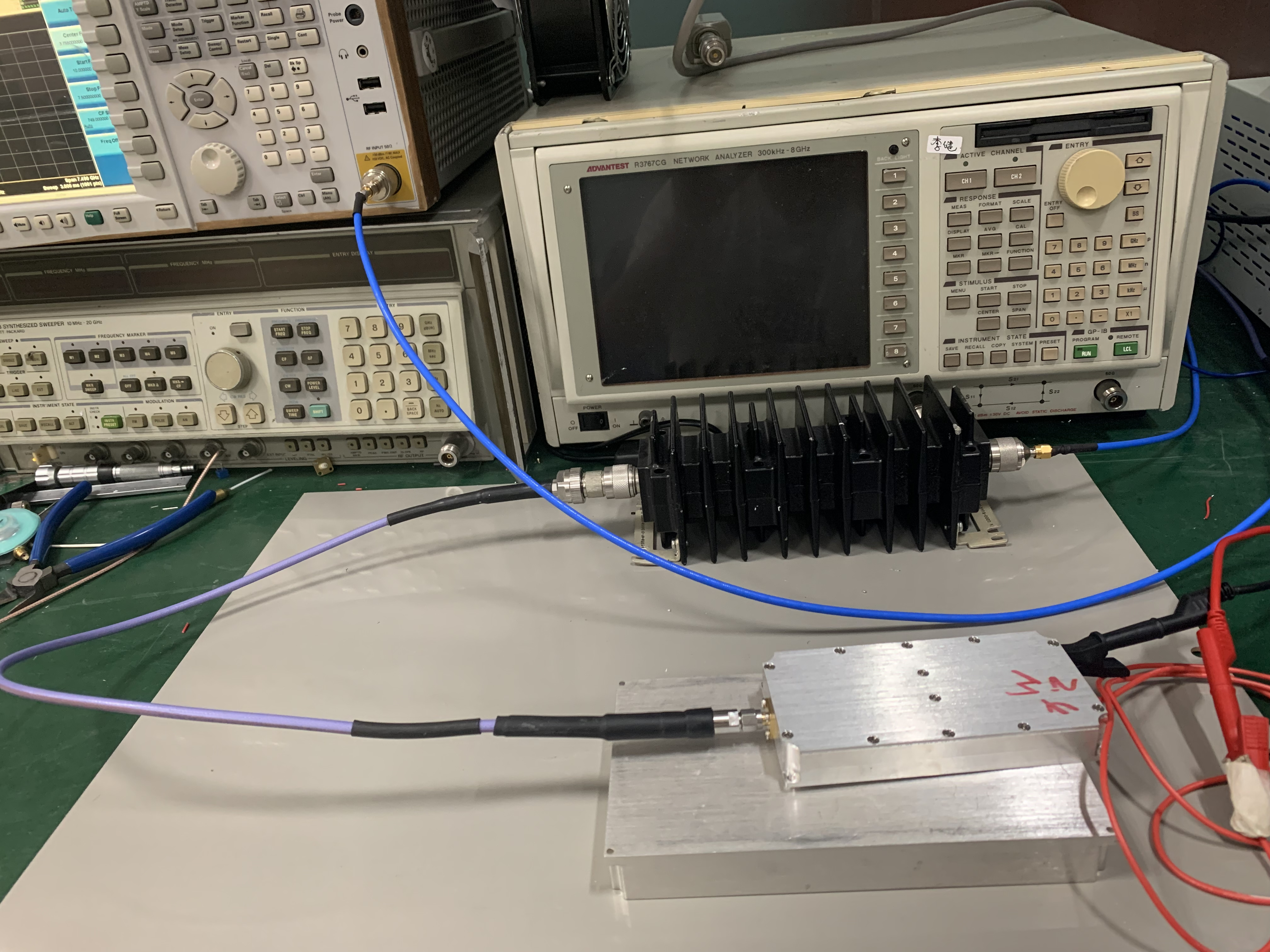
l After the equipment is set up, connect the power supply of the product to the DC power supply(pay attention to the positive and negative poles), the output of the product is linked to the attenuator through the RF cable, and the attenuator is linked to the spectrum analyzer through the RF cable (note that the product cannot be directly linked to the spectrum analyzer, must pass through the attenuator before linking to the spectrum analyzer).
l After the instrument is connected and debugged, turn on the power, read the power value in the spectrum analyzer, and read the current in the DC power supply.
l During the test,pay attention to the heat dissipation of the product, and add a radiator to the bottom of the product.
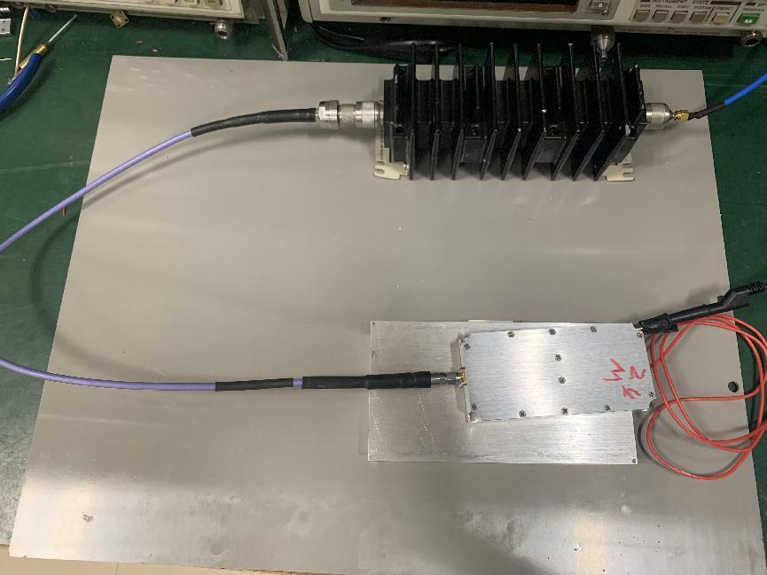
Test Picture
1. Rf Power module connect to attenuator
2. voltage and current when test
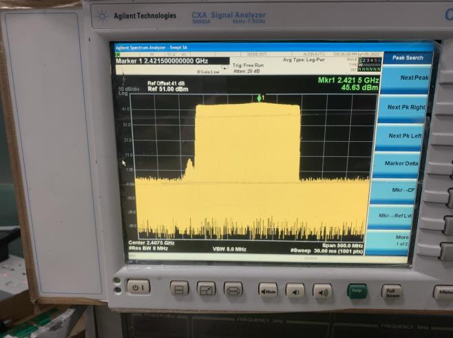
3. Product test waveform
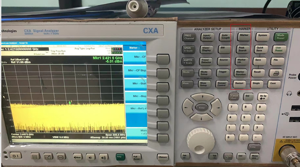
4. Mark set button


We use cookies to offer you a better browsing experience, analyze site traffic and personalize content. By using this site, you agree to our use of cookies.
Privacy Policy